CSOUND Español
CSOUND AND ARDUINO
CSOUND Y ARDUINO
It is the intention of this chapter to suggest a number of ways in which Csound can be paired with an Arduino prototyping circuit board. It is not the intention of this chapter to go into any detail about how to use an Arduino, there is already a wealth of information available elsewhere online about this. It is common to use an Arduino and Csound with another program functioning as an interpreter, so therefore some time is spent discussing these other programs.
La intención de este capítulo es sugerir varias maneras en las que Csound puede ser emparejado con una placa de prototipos Arduino. No es la intención de este capítulo entrar en ningún detalle acerca de cómo usar un Arduino, ya hay una gran cantidad de información disponible en otros sitios en línea sobre esto. Es común usar un Arduino y Csound con otro programa que funcione como un intérprete, así que por lo tanto se gasta algún tiempo discutiendo estos otros programas.
An Arduino is a simple microcontroller circuit board that has become enormously popular as a component in multidisciplinary and interactive projects for musicians and artists since its introduction in 2005. An Arduino board can be programmed to do many things and to send and receive data to and from a wide variety of other components and devices. As such it is impossible to specifically define its function here. An Arduino is normally programmed using its own development environment (IDE). A program is written on a computer which is then uploaded to the Arduino; the Arduino then runs this program, independent of the computer if necessary. Arduino's IDE is based on that used by Processing and Wiring. Arduino programs are often referred to as "sketches". There now exists a plethora of Arduino variants and even a number of derivatives and clones but all function in more or less the same way.
Un Arduino es una placa de circuito simple del microcontrolador que se ha convertido en enormemente popular como componente en proyectos multidisciplinarios e interactivos para los músicos y los artistas desde su introducción en 2005. Un tablero de Arduino se puede programar para hacer muchas cosas y para enviar y recibir datos ay desde Una amplia variedad de otros componentes y dispositivos. Como tal, es imposible definir específicamente su función aquí. Un Arduino normalmente se programa utilizando su propio entorno de desarrollo (IDE). Un programa se escribe en una computadora que se carga en el Arduino; El Arduino entonces ejecuta este programa, independiente de la computadora si es necesario. El IDE de Arduinos se basa en el utilizado por Processing and Wiring. Los programas de Arduino se refieren a menudo como bocetos. Ahora existe una plétora de variantes de Arduino e incluso un número de derivados y clones pero todos funcionan más o menos de la misma manera.
Interaction between an Arduino and Csound is essentially a question of communication and as such a number of possible solutions exist. This chapter will suggest several possibilities and it will then be up to the user to choose the one most suitable for their requirements. Most Arduino boards communicate using serial communication (normally via a USB cable). A number of Arduino programs, called "Firmata", exist that are intended to simplify and standardise communication between Arduinos and software. Through the use of a Firmata the complexity of Arduino's serial communication is shielded from the user and a number of simpler objects, ugens or opcodes (depending on what the secondary software is) can instead be used to establish communication. Unfortunately Csound is rather poorly served with facilities to communicate using the Firmata (although this will hopefully improve in the future) so it might prove easiest to use another program (such as Pd or Processing) as an intermediary between the Arduino and Csound.
La interacción entre un Arduino y Csound es esencialmente una cuestión de comunicación y como tal un número de posibles soluciones existen. Este capítulo sugiere varias posibilidades y será entonces el usuario quien elija el más adecuado para sus necesidades. La mayoría de las tarjetas Arduino se comunican mediante comunicación serie (normalmente a través de un cable USB). Existe una serie de programas de Arduino, denominados Firmata, que tienen como objetivo simplificar y estandarizar la comunicación entre Arduinos y el software. Mediante el uso de una Firmata, la complejidad de la comunicación en serie de Arduinos está protegida del usuario y una serie de objetos más simples, ugens u opcodes (dependiendo de lo que es el software secundario) puede ser utilizado para establecer la comunicación. Desafortunadamente Csound es bastante mal servido con facilidades para comunicarse usando el Firmata (aunque esto se espera mejorar en el futuro) por lo que podría resultar más fácil de usar otro programa (como Pd o Procesamiento) como un intermediario entre el Arduino y Csound.
Arduino - Pd - Csound Arduino - Pd - Csound
First we will consider communication between an Arduino (running a Standard Firmata) and Pd. Later we can consider the options for further communication from Pd to Csound.
Primero consideraremos la comunicación entre un Arduino (ejecutando una Firma Estándar) y un Pd. Posteriormente podemos considerar las opciones para una mayor comunicación de Pd a Csound.
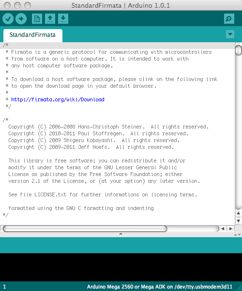
Assuming that the Arduino IDE (integrated development environment) has been installed and that the Arduino has been connected, we should then open and upload a Firmata sketch. One can normally be found by going to File -> Examples -> Firmata -> ... There will be a variety of flavours from which to choose but "StandardFirmata" should be a good place to start. Choose the appropriate Arduino board type under Tools -> Board -> ... and then choose the relevant serial port under Tools -> Serial Port -> ... Choosing the appropriate serial port may require some trial and error but if you have chosen the wrong one this will become apparent when you attempt to upload the sketch. Once you have established the correct serial port to use, it is worth taking a note of which number on the list (counting from zero) this corresponds to as this number will be used by Pd to communicate with the Arduino. Finally upload the sketch by clicking on the right-pointing arrow button.
Suponiendo que se haya instalado el IDE de Arduino (entorno de desarrollo integrado) y que se haya conectado el Arduino, debemos abrir y cargar un croquis Firmata. Normalmente se puede encontrar al ir a Archivo - Ejemplos - Firma - ... Habrá una variedad de sabores de los que elegir, pero StandardFirmata debe ser un buen lugar para comenzar. Elija el tipo de placa Arduino adecuado en Herramientas - Tablero - ... y elija el puerto serie correspondiente en Herramientas - Puerto serie - ... La elección del puerto serie adecuado puede requerir un cierto ensayo y error, pero si ha elegido el incorrecto este Se pondrán de manifiesto cuando intente cargar el boceto. Una vez que haya establecido el puerto serie correcto para usar, vale la pena tomar una nota de qué número en la lista (contando desde cero) esto corresponde a como este número será utilizado por Pd para comunicarse con el Arduino. Finalmente cargue el croquis haciendo clic en el botón de flecha hacia la derecha.
Assuming that Pd is already installed, it will also be necessary to install an add-on library for Pd called Pduino. Follow its included instructions about where to place this library on your platform and then reopen Pd. You will now have access to a set of Pd objects for communicating with your Arduino. The Pduino download will also have included a number of examples Pd. "arduino-test.pd" will probably be the best patch to start. First set the appropriate serial port number to establish communication and then set Arduino pins as "input", "output" etc. as you desire. It is beyond the scope of this chapter to go into further detail regarding setting up an Arduino with sensors and auxiliary components, suffice to say that communication to an Arduino is normally tested by 'blinking' digital pin 13 and communication from an Arduino is normally tested by connecting a 10 kilo-ohm (10k) potentiometer to analog pin zero. For the sake of argument, we shall assume in this tutorial that we are setting the Arduino as a hardware controller and have a potentiometer connected to pin 0.
Suponiendo que Pd ya esté instalado, también será necesario instalar una biblioteca complementaria para Pd llamada Pduino. Siga las instrucciones incluidas sobre dónde colocar esta biblioteca en su plataforma y luego vuelva a abrir Pd. Ahora tendrá acceso a un conjunto de objetos Pd para comunicarse con su Arduino. La descarga de Pduino también incluirá una serie de ejemplos Pd. Arduino-test.pd probablemente será el mejor parche para empezar. Primero, establezca el número de puerto serie apropiado para establecer la comunicación y, a continuación, configure los pines Arduino como entrada, salida, etc., según desee. Es más allá del alcance de este capítulo para entrar en más detalle con respecto a la configuración de un Arduino con sensores y componentes auxiliares, basta con decir que la comunicación a un Arduino es normalmente probado por parpadeo pin digital 13 y la comunicación de un Arduino se prueba normalmente mediante la conexión Un potenciómetro de 10 kilo-ohmios (10k) al pin analógico cero. En aras del argumento, asumiremos en este tutorial que estamos configurando el Arduino como controlador de hardware y tenemos un potenciómetro conectado al pin 0.

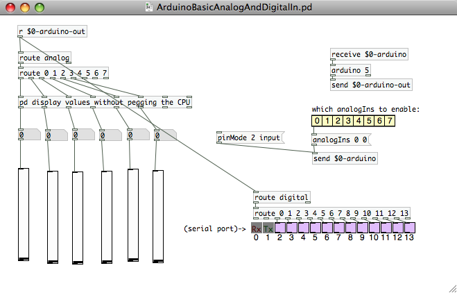
This picture below demonstrates a simple Pd patch that uses Pduino's objects to receive communication from Arduino's analog and digital inputs. (Note that digital pins 0 and 1 are normally reserved for serial communication if the USB serial communication is unavailable.) In this example serial port '5' has been chosen. Once the analogIns enable box for pin 0 is checked, moving the potentiometer will change the values in the left-most number box (and move the slider connected to it). Arduino's analog inputs generate integers with 10-bit resolution (0 - 1023) but these values will often be rescaled as floats within the range 0 - 1 in the host program for convenience.
Esta imagen a continuación muestra un parche Pd simple que utiliza objetos Pduinos para recibir comunicación desde entradas analógicas y digitales Arduinos. (Tenga en cuenta que las clavijas digitales 0 y 1 están normalmente reservadas para comunicación serie si la comunicación serie USB no está disponible.) En este ejemplo se ha elegido el puerto serie 5. Una vez que se comprueba la caja de habilitación de analogIns para el pin 0, mover el potenciómetro cambiará los valores en el cuadro de número más a la izquierda (y moverá el deslizador conectado a él). Las entradas analógicas de Arduinos generan números enteros con una resolución de 10 bits (0 - 1023), pero estos valores a menudo se reescalonarán como flotadores dentro del rango 0 - 1 en el programa host por conveniencia.
Having established communication between the Arduino and Pd we can now consider the options available to us for communicating between Pd and Csound. The most obvious (but not necessarily the best or most flexible) method is to use Pd's csoundapi~ object (csound6~ in Csound6). The above example could be modified to employ csoundapi~ as shown below.
Una vez establecida la comunicación entre el Arduino y el Pd, ahora podemos considerar las opciones disponibles para comunicarnos entre Pd y Csound. El método más obvio (pero no necesariamente el mejor o más flexible) es usar Pds csoundapi ~ object (csound6 ~ en Csound6). El ejemplo anterior podría modificarse para emplear csoundapi ~ como se muestra a continuación.
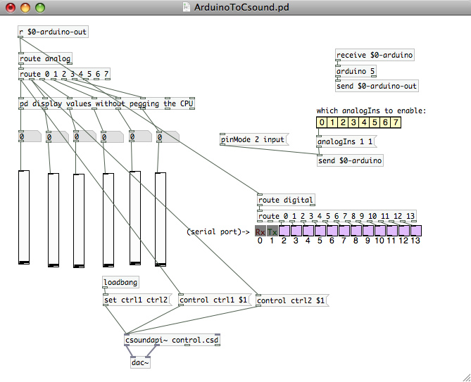
The outputs from the first two Arduino analog controls are passed into Csound using its API. Note that we should use the unpegged (not quantised in time) values directly from the 'route' object. The Csound .csd file 'control.csd' is called upon by Pd and it should reside in the same directory as the Pd patch. Establishing communication to and from Pd could employ code such as that shown below. Data from controller one (Arduino analog 0) is used to modulate the amplitude of an oscillator and data from controller two (Arduino analog 1) varies its pitch across a four octave range.
Las salidas de los dos primeros controles analógicos de Arduino se pasan a Csound usando su API. Tenga en cuenta que debemos utilizar los valores sin ajustar (no cuantificados en el tiempo) directamente desde el objeto de ruta. El archivo Csound .csd control.csd es llamado por Pd y debe residir en el mismo directorio que el parche Pd. Establecer comunicación ay desde Pd podría emplear código como el que se muestra a continuación. Los datos del controlador uno (análogo Arduino 0) se utilizan para modular la amplitud de un oscilador y los datos del controlador dos (análogo 1 de Arduino) varían su tono a través de un rango de cuatro octavas.
EXAMPLE 08B01_Pd_to_Csound.csd
<CsoundSynthesizer>

<CsOptions>
</CsOptions>

<CsInstruments>

sr = 44100
nchnls = 2
0dbfs = 1
ksmps = 32

 instr 1
; read in controller data from Pd via the API using 'invalue'
kctrl1  invalue  "ctrl1"
kctrl2  invalue  "ctrl2"
; re-range controller values from 0 - 1 to 7 - 11
koct    =        (kctrl2*4)+7
; create an oscillator
a1      vco2     kctrl1,cpsoct(koct),4,0.1
        outs     a1,a1
 endin
</CsInstruments>

<CsScore>
i 1 0 10000
e
</CsScore>

</CsoundSynthesizer>
Communication from Pd into Csound is established using the invalue opcodes and audio is passed back to Pd from Csound using outs. Note that Csound does not address the computer's audio hardware itself but merely passes audio signals back to Pd. Greater detail about using Csound within Pd can be found in the chapter Csound in Pd.
La comunicación de Pd en Csound se establece usando los opcodes invaluables y el audio se pasa de nuevo a Pd de Csound usando salidas. Tenga en cuenta que Csound no se dirige al hardware de audio de las computadoras en sí, sino que simplemente transmite señales de audio a Pd. Mayor detalle sobre el uso de Csound dentro de Pd se puede encontrar en el capítulo Csound en Pd.
A disadvantage of using the method is that in order to modify the Csound patch it will require being edited in an external editor, re-saved, and then the Pd patch will need to be reloaded to reflect these changes. This workflow might be considered rather inefficient.
Una desventaja de usar el método es que para modificar el parche Csound necesitará ser editado en un editor externo, vuelto a guardar, y entonces el parche Pd tendrá que ser recargado para reflejar estos cambios. Este flujo de trabajo puede considerarse bastante ineficiente.
Another method of data communication between PD and Csound could be to use MIDI. In this case some sort of MIDI connection node or virtual patchbay will need to be employed. On Mac this could be the IAC driver, on Windows this could be MIDI Yoke and on Linux this could be Jack. This method will have the disadvantage that the Arduino's signal might have to be quantised in order to match the 7-bit MIDI controller format but the advantage is that Csound's audio engine will be used (not Pd's; in fact audio can be disabled in Pd) so that making modifications to the Csound .csd and hearing the changes should require fewer steps.
Otro método de comunicación de datos entre PD y Csound podría ser el uso de MIDI. En este caso, necesitará emplear algún tipo de nodo de conexión MIDI o patchbay virtual. En Mac esto podría ser el controlador de IAC, en Windows esto podría ser MIDI Yoke y en Linux esto podría ser Jack. Este método tendrá la desventaja de que la señal de Arduinos podría tener que ser cuantificada para coincidir con el formato de controlador MIDI de 7 bits, pero la ventaja es que se utilizará el motor de audio Csounds (no Pds, de hecho el audio se puede deshabilitar en Pd) De modo que hacer modificaciones al Csound .csd y escuchar los cambios debería requerir menos pasos.
A final method for communication between Pd and Csound is to use OSC. This method would have the advantage that analog 10 bit signal would not have to be quantised. Again workflow should be good with this method as Pd's interaction will effectively be transparent to the user and once started it can reside in the background during working. Communication using OSC is also used between Processing and Csound so is described in greater detail below.
Un método final para la comunicación entre Pd y Csound es usar OSC. Este método tendría la ventaja de que la señal analógica de 10 bits no tendría que ser cuantificada. De nuevo el flujo de trabajo debe ser bueno con este método como la interacción de Pds será efectivamente transparente para el usuario y una vez que se inició puede residir en el fondo durante el trabajo. La comunicación usando OSC también se utiliza entre Processing y Csound por lo que se describe con mayor detalle a continuación.
Arduino - Processing - Csound
Arduino - Procesamiento - Csound
It is easy to communicate with an Arduino using a Processing sketch and any data within Processing can be passed to Csound using OSC.
Es fácil comunicarse con un Arduino usando un boceto de Procesamiento y cualquier dato dentro de Procesamiento se puede pasar a Csound usando OSC.
The following method makes use of the Arduino and P5 (glove) libraries for processing. Again these need to be copied into the appropriate directory for your chosen platform in order for Processing to be able to use them. Once again there is no requirement to actually know very much about Processing beyond installing it and running a patch (sketch). The following sketch will read all Arduino inputs and output them as OSC.
El siguiente método hace uso de las bibliotecas Arduino y P5 (guante) para su procesamiento. Nuevamente éstos deben ser copiados en el directorio apropiado para la plataforma elegida para que el procesamiento pueda usarlos. Una vez más no hay ningún requisito para saber realmente mucho sobre el proceso más allá de instalarlo y ejecutar un parche (croquis). El siguiente boceto leerá todas las entradas de Arduino y las emitirá como OSC.

Start the Processing sketch by simply clicking the triangle button at the top-left of the GUI. Processing is now reading serial data from the Arduino and transmitting this as OSC data within the computer.
Inicie el boceto de Procesamiento simplemente haciendo clic en el botón de triángulo situado en la parte superior izquierda de la GUI. El procesamiento está leyendo datos en serie desde el Arduino y transmitiéndolos como datos OSC dentro del ordenador.
The OSC data sent by Processing can be read by Csound using its own OSC opcodes. The following example simply reads in data transmitted by Arduino's analog pin 0 and prints changed values to the terminal. To read in data from all analog and digital inputs you can use this example .csd.
Los datos OSC enviados por Processing pueden ser leídos por Csound usando sus propios opcodes OSC. El siguiente ejemplo lee simplemente los datos transmitidos por el pin analógico 0 de Arduinos e imprime los valores cambiados al terminal. Para leer los datos de todas las entradas analógicas y digitales puede utilizar este ejemplo .csd.
EXAMPLE 08B02_Processing_to_Csound.csd
<CsoundSynthesizer>

<CsOptions>
-o dac
</CsOptions>

<CsInstruments>

sr = 44100
ksmps = 8
nchnls = 1
0dbfs = 1

; handle used to reference osc stream
gihandle OSCinit 12001

 instr 1
; initialise variable used for analog values
gkana0      init       0
; read in OSC channel '/analog/0'
gktrigana0  OSClisten  gihandle, "/analog/0", "i", gkana0
; print changed values to terminal
            printk2    gkana0
 endin

</CsInstruments>

<CsScore>
i 1 0 3600
e
</CsScore>

</CsoundSynthesizer>
Also worth in investigating is Jacob Joaquin's Csoundo - a Csound library for Processing. This library will allow closer interaction between Processing and Csound in the manner of the csoundapi~ object in Pd. This project has more recently been developed by Rory Walsh.
También vale la pena investigar es Jacob Joaquins Csoundo - una biblioteca Csound para procesamiento. Esta biblioteca permitirá una interacción más estrecha entre procesamiento y Csound en la forma del objeto csoundapi ~ en Pd. Este proyecto ha sido desarrollado más recientemente por Rory Walsh.
Arduino as a MIDI Device
Arduino como un dispositivo MIDI
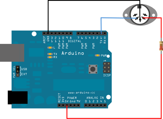
Some users might find it most useful to simply set the Arduino up as a MIDI device and to use that protocol for communication. In order to do this all that is required is to connect MIDI pin 4 to the Arduino's 5v via a 200k resistor, to connect MIDI pin 5 to the Arduino's TX (serial transmit) pin/pin 1 and to connect MIDI pin 2 to ground, as shown below. In order to program the Arduino it will be necessary to install Arduino's MIDI library.
Algunos usuarios pueden encontrar que es más útil simplemente configurar el Arduino como un dispositivo MIDI y usar ese protocolo para la comunicación. Para ello basta con conectar el pin MIDI 4 al Arduinos 5v a través de una resistencia de 200k, conectar el pin MIDI 5 al pin / pin 1 de Arduinos TX y conectar el pin 2 a tierra, Como se muestra abajo. Para programar el Arduino será necesario instalar la biblioteca MIDI de Arduinos.
Programming an Arduino to generate a MIDI controller signal from analog pin 0 could be done using the following code:
La programación de un Arduino para generar una señal de controlador MIDI desde el pin analógico 0 podría hacerse usando el código siguiente:
// example written by Iain McCurdy
// import midi library
#include <MIDI.h>

const int analogInPin = A0; // choose analog input pin
int sensorValue = 0;        // sensor value variable
int oldSensorValue = 0;     // sensor value from previous pass
int midiChannel = 1;        // set MIDI channel

void setup()
{
 MIDI.begin(1);
}

void loop()
{
  sensorValue = analogRead(analogInPin);

  // only send out a MIDI message if controller has changed
  if (sensorValue!=oldSensorValue)
    {
    // controller 1, rescale value from 0-1023 (Arduino) to 0-127 (MIDI)
    MIDI.sendControlChange(1,sensorValue/8,midiChannel);
    oldSensorValue = sensorValue; // set old sensor value to current
    }
  }


  delay(10);
}
Data from the Arduino can now be read using Csound's ctrl7 opcodes for reading MIDI controller data.
Los datos del Arduino ahora se pueden leer usando Csounds ctrl7 opcodes para leer los datos del controlador MIDI.
The Serial Opcodes
Las Opcodes Seriales
Serial data can also be read directly from the Arduino by Csound by using Matt Ingalls' opcodes for serial communication: serialBegin and serialRead.
Los datos en serie también se pueden leer directamente desde el Arduino de Csound usando los opcodes de Matt Ingalls para la comunicación serial: serialBegin y serialRead.
An example Arduino sketch for serial communication could be as simple as this:
Un ejemplo de boceto de Arduino para la comunicación serial podría ser tan sencillo como esto:
// Example written by Matt Ingalls
// ARDUINO CODE:

void setup()  {
  // enable serial communication
  Serial.begin(9600);

  // declare pin 9 to be an output:
  pinMode(9, OUTPUT);
}

void loop()
{
  // only do something if we received something (this should be at csound's k-rate)
  if (Serial.available())
  {

         // set the brightness of LED (connected to pin 9) to our input value
       int brightness = Serial.read();
       analogWrite(9, brightness);

       // while we are here, get our knob value and send it to csound
       int sensorValue = analogRead(A0);
       Serial.write(sensorValue/4); // scale to 1-byte range (0-255)
  }
}
It will be necessary to provide the correct address of the serial port to which the Arduino is connected (in the given example the Windows platform was being used and the port address was /COM4).
Será necesario proporcionar la dirección correcta del puerto serie al que está conectado el Arduino (en el ejemplo dado se estaba utilizando la plataforma Windows y la dirección del puerto era / COM4).
It will be necessary to scale the value to correspond to the range provided by a single byte (0-255) so therefore the Arduino's 10 bit analog input range (0-1023) will have to be divided by four.
Será necesario escalar el valor para que corresponda al rango proporcionado por un solo byte (0-255), por lo que el rango de entrada analógica de 10 bits de Arduinos (0-1023) tendrá que ser dividido por cuatro.
EXAMPLE 08B03_Serial_Read.csd
; Example written by Matt Ingalls
; CSOUND CODE:
; run with a commandline something like:
; csound --opcode-lib=serialOpcodes.dylib serialdemo.csd -odac -iadc

<CsoundSynthesizer>

<CsOptions>

</CsOptions>
;--opcode-lib=serialOpcodes.dylib -odac
<CsInstruments>

ksmps = 500 ; the default krate can be too fast for the arduino to handle
0dbfs = 1

instr 1
	iPort	serialBegin	"/COM4", 9600
	kVal	serialRead 	iPort
		printk2		kVal
endin


</CsInstruments>
<CsScore>
i 1 0 3600
e
</CsScore>
</CsoundSynthesizer>
This example will read serial data from the Arduino and print it to the terminal. Reading output streams from several of Arduino's sensor inputs simultaneously will require more complex parsing of data within Csound as well as more complex packaging of data from the Arduino. This is demonstrated in the following example which also shows how to handle serial transmission of integers larger than 255 (the Arduino analog inputs have 10 bit resolution).
Este ejemplo lee los datos en serie del Arduino y los imprime al terminal. La lectura de flujos de salida de varias entradas de sensores Arduinos simultáneamente requerirá un análisis más complejo de datos dentro de Csound, así como un empaquetado más complejo de datos del Arduino. Esto se demuestra en el siguiente ejemplo que también muestra cómo manejar la transmisión en serie de enteros mayores de 255 (las entradas analógicas de Arduino tienen una resolución de 10 bits).
First the Arduino sketch, in this case reading and transmitting two analog and one digital input:
Primero el esbozo de Arduino, en este caso lectura y transmisión de dos entradas analógicas y una digital:
// Example written by Sigurd Saue
// ARDUINO CODE:

// Analog pins
int potPin = 0;
int lightPin = 1;

// Digital pin
int buttonPin = 2;

// Value IDs (must be between 128 and 255)
byte potID = 128;
byte lightID = 129;
byte buttonID = 130;

// Value to toggle between inputs
int select;

/*
** Two functions that handles serial send of numbers of varying length
*/

// Recursive function that sends the bytes in the right order
void serial_send_recursive(int number, int bytePart)
{
  if (number < 128) {        // End of recursion
    Serial.write(bytePart);  // Send the number of bytes first
  }
  else {
    serial_send_recursive((number >> 7), (bytePart + 1));
  }
  Serial.write(number % 128);  // Sends one byte
}

void serial_send(byte id, int number)
{
  Serial.write(id);
  serial_send_recursive(number, 1);
}

void setup()  {
  // enable serial communication
  Serial.begin(9600);
  pinMode(buttonPin, INPUT);
}

void loop()
{
  // Only do something if we received something (at csound's k-rate)
  if (Serial.available())
  {
      // Read the value (to empty the buffer)
       int csound_val = Serial.read();

       // Read one value at the time (determined by the select variable)
       switch (select) {
         case 0: {
           int potVal = analogRead(potPin);
           serial_send(potID, potVal);
         }
         break;
         case 1: {
           int lightVal = analogRead(lightPin);
           serial_send(lightID, lightVal);
         }
         break;
         case 2: {
           int buttonVal = digitalRead(buttonPin);
           serial_send(buttonID, buttonVal);
         }
         break;
       }

       // Update the select (0, 1 and 2)
       select = (select+1)%3;
  }
}
The solution is similar to MIDI messages. You have to define an ID (a unique number >= 128) for every sensor. The ID behaves as a status byte that clearly marks the beginning of a message received by Csound. The remaining bytes of the message will all have a most significant bit equal to zero (value < 128). The sensor values are transmitted as ID, length (number of data bytes), and the data itself. The recursive function serial_send_recursive counts the number of data bytes necessary and sends the bytes in the correct order. Only one sensor value is transmitted for each run through the Arduino loop.
La solución es similar a los mensajes MIDI. Debe definir un ID (un número único = 128) para cada sensor. El ID se comporta como un byte de estado que marca claramente el comienzo de un mensaje recibido por Csound. Los bytes restantes del mensaje tendrán todos un bit más significativo igual a cero (valor 128). Los valores del sensor se transmiten como ID, longitud (número de bytes de datos) y los datos en sí. La función recursiva serial_send_recursive cuenta el número de bytes de datos necesarios y envía los bytes en el orden correcto. Sólo se transmite un valor de sensor para cada ejecución a través del bucle Arduino.
The Csound code receives the values with the ID first. Of course you have to make sure that the IDs in the Csound code matches the ones in the Arduino sketch. Here's an example of a Csound orchestra that handles the messages sent from the Arduino sketch:
El código Csound recibe los valores con el ID primero. Por supuesto, debe asegurarse de que los IDs del código Csound coincidan con los del boceto de Arduino. Heres un ejemplo de una orquesta de Csound que maneja los mensajes enviados del bosquejo de Arduino:
EXAMPLE 08B04_Serial_Read_multiple.csd
; Example written by Sigurd Saue
; CSOUND CODE:
<CsoundSynthesizer>
<CsOptions>
-d -odac
</CsOptions>
<CsInstruments>

sr  = 44100
ksmps = 500 ; the default krate can be too fast for the arduino to handle
nchnls = 2
0dbfs  = 1

giSaw  ftgen 0, 0, 4096, 10, 1, 1/2, 1/3, 1/4, 1/5, 1/6, 1/7, 1/8

instr 1

; Initialize the three variables to read
kPot 	init 0
kLight 	init 0
kButton init 0

iPort	serialBegin "/COM5", 9600 ;connect to the arduino with baudrate = 9600
	serialWrite iPort, 1	;Triggering the Arduino (k-rate)

kValue 	= 0
kType 	serialRead iPort	; Read type of data (pot, light, button)

if (kType >= 128) then

	kIndex = 0
	kSize  serialRead iPort

	loopStart:
	    kValue 	= kValue << 7
	    kByte	serialRead iPort
	    kValue 	= kValue + kByte
	    loop_lt kIndex, 1, kSize, loopStart
endif

if (kValue < 0) kgoto continue

if (kType == 128) then		; This is the potmeter
	kPot 	= kValue
elseif (kType == 129) then	; This is the light
	kLight 	= kValue
elseif (kType == 130) then	; This is the button (on/off)
	kButton = kValue
endif

continue:

; Here you can do something with the variables kPot, kLight and kButton
; printks "Pot %f\n", 1, kPot
; printks "Light %f\n", 1, kLight
; printks "Button %d\n", 1, kButton

; Example: A simple oscillater controlled by the three parameters
kAmp	port	kPot/1024, 0.1
kFreq	port	(kLight > 100 ? kLight : 100), 0.1
aOut 	oscil 	kAmp, kFreq, giSaw

if (kButton == 0) then
	out 	aOut
endif

endin

</CsInstruments>
<CsScore>
i 1 0 60	; Duration one minute
e
</CsScore>
</CsoundSynthesizer>
Remember to provide the correct address of the serial port to which the Arduino is connected (the example uses "/COM5").
Recuerde proporcionar la dirección correcta del puerto serie al que está conectado el Arduino (el ejemplo usa / COM5).
HID
Another option for communication has been made available by a new Arduino board called "Leonardo". It pairs with a computer as if it were an HID (Human Interface Device) such as a mouse, keyboard or a gamepad. Sensor data can therefore be used to imitate the actions of a mouse connected to the computer or keystrokes on a keyboard. Csound is already equipped with opcodes to make use of this data. Gamepad-like data is perhaps the most useful option though and there exist opcodes (at least in the Linux version) for reading gamepad data. It is also possible to read in data from a gamepad using pygame and Csound's python opcodes.
Otra opción para la comunicación ha sido puesta a disposición por un nuevo consejo de Arduino llamado Leonardo. Se empareja con una computadora como si fuera un HID (Human Interface Device), como un ratón, un teclado o un gamepad. Por lo tanto, los datos del sensor pueden usarse para imitar las acciones de un ratón conectado al ordenador o las pulsaciones de teclas en un teclado. Csound ya está equipado con opcodes para hacer uso de estos datos. Gamepad-como datos es quizás la opción más útil sin embargo y existen opcodes (al menos en la versión de Linux) para la lectura de datos gamepad. También es posible leer en los datos de un gamepad usando Pygame y Csounds python opcodes.